Shaders: Parallax Effect for a Brick Wall
Table of Contents
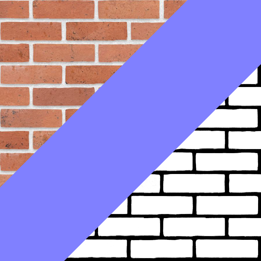
The Parallax Effect is the apparent displacement of an object when observed from two lines of sight. Close to viewpoint objects move little, while far objects seem to move farther.
It is one of those effects I have been obsessed with learning for years. It is a very useful technique that can be applied in a very wide range of materials, such as: brick walls (see the gif above, I did that!), cracked ice, elegant floors, building interiors seen from the outside… and much, much, more.
The Technique Itself⌗
Take a texture and offset it along the view direction (in tangent space) as many times as needed.
The View Direction in Tangent Space means the vector that passes tangentially through a vertex in the mesh, and corresponds to the direction our camera is pointing.
For the brick wall and the cracked ice, we offset a mask that we later blend with the actual texture. This is certainly not the case for every parallax effect, but it is a nice starting point.
The Brick Wall⌗
At first, I followed the tutorials cited in the Bibliography section. One link leads to the others, so feel free to explore.
I got the main texture from here. I then jumped into Photoshop and created the mask (black and white). I also got the flat bump map flat colour from an article at Unity’s website.
ShaderGraph - Only nodes⌗
I followed tutorials but ended up changing the effect to my needs. I realized that painting bricks coming out of a wall is not the same to paint cracks going into the ice. And they need to come out, because, unlike ice, bricks are not transparent and the effect would not sell well.
Another key difference is that I have exposed all variables. I used to be a Tools and Gameplay Programmer, so I am always looking for reusability. This means not having any variables hardcoded into materials if they would be of interest to the artist or designer.

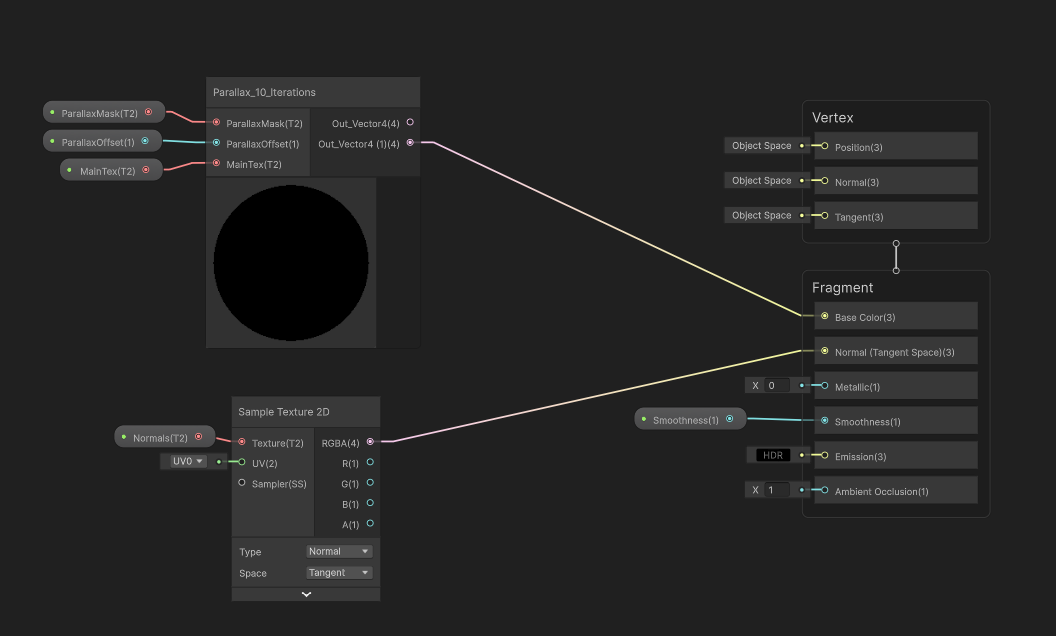
We take the View Direction in Tanget Space to the fragment, multiply it with the desired offset, and use that to offset the mask. The Tilling and Offset node is just creating a custom set of UVs —our modified UVs— to sample the Parallax Mask.
With this, we would have enough for the simplest Parallax Effect, so I kept it as one subgraph.
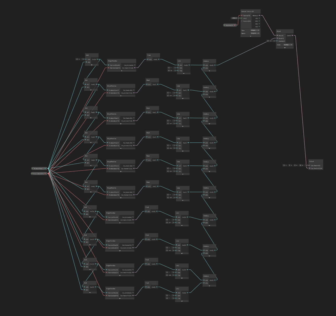
And now, do that ten times.
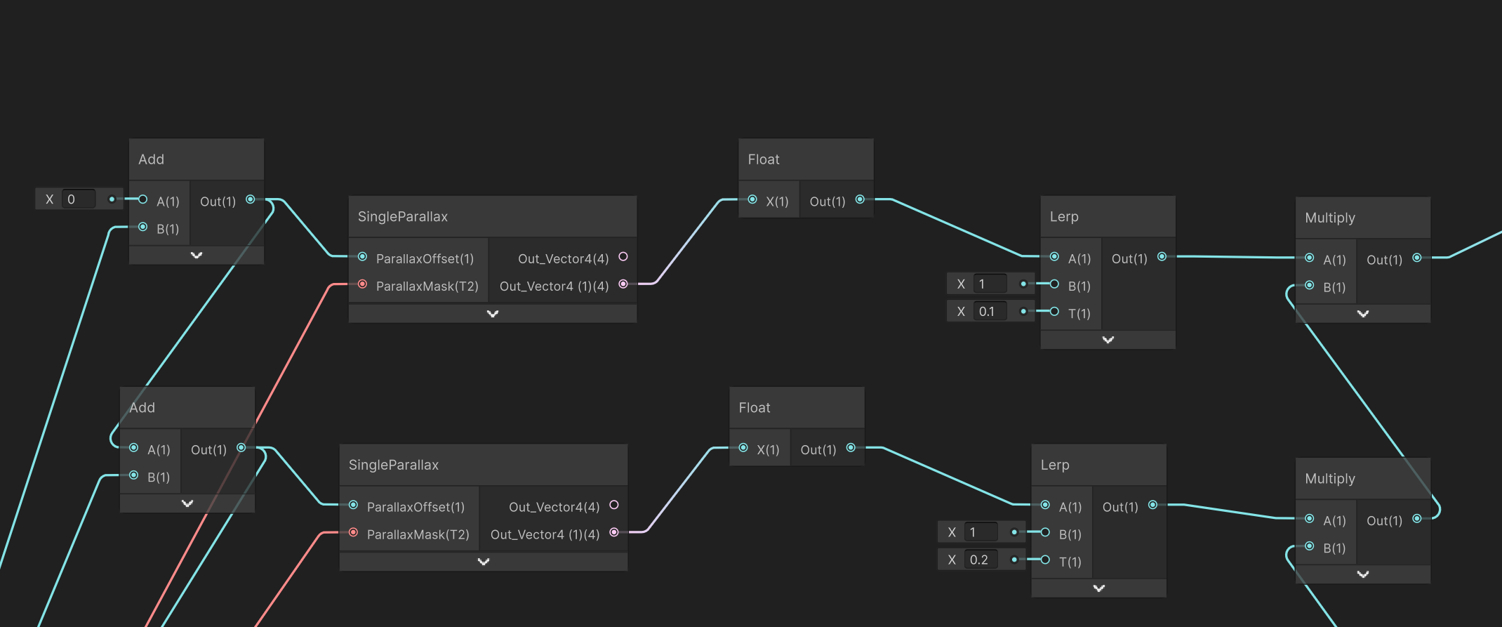
Each iteration, we take the offset and add it to itself. The first time, we add it to 0. Subsequently, we take the result of this operation and take it to another Add Node, whose second argument will be the defined offset, effectively repeating this pattern.
We take that offset into our Single Parallax subgraph, and the Parallax Mask. Since we are using a mask, the result of the Single Parallax node will be in black and white, which can be expressed as a float.
For this effect, we are fading the mask the farther it is from the surface of the object. For this, we are going to lerp between the parallax value and 1. The amount we lerp (T) is going to be greater the deeper we get into the iterations. Since this is manual, start with 0.1 and increment 0.1 each time.
⚠ I realized while writing this that the last iteration’s T is 1, so it is useless and should be removed. I left it in because I was more interested in building on top of it in the following sections.
We then multiply each iteration with the previous and blend that with the main texture.
🔍 The Cracked Ice tutorial inverts the colour of the mask, which highlights the cracks. I want to bring out the bricks, so I have removed that bit.
Main texture goes to Base Color, add Normals in, and done.

ShaderGraph - Custom Code nodes⌗
This is good and all, but I am not satisfied. Repeating all those nodes is ugly, and I do not have any control over how many iterations happen on this parallax effect. Furthermore, I could want a different increment per iteration, or a different lerp increment value.
Also, having code for this will be useful if I ever want to port the effect to engines that do not sport a node-based shader making tool.
But most importantly, I want to make sure I am understanding this right.
For this reason, I have modified my Shadergraph to use a custom function node:

I need to pass the View Direction from Shadergraph, since it can only be calculated at the vertex pass.
I also needed the UVs, the mask, the offset and the new variable: depth, which tells the script how many iterations we want. I will respect the offset addition as is, and calculate the lerping as an evenly distributed sequence (but fixing the last iteration problem).
The MainTex is then blended in as before, by using the Shadergraph Node.
The code for one iteration would be:
void Parallax_float(
  float3 viewDir,
  float2 uv,
  UnityTexture2D mask,
  float parallaxOffset,
  float depth,
  out float4 Out)
{
    // One iteration
    float2 maskOffset = viewDir * parallaxOffset;
    float4 maskColor =
      SAMPLE_TEXTURE2D(mask.tex, mask.samplerstate, uv + maskOffset);

    Out = maskColor;
}
And now, with a for loop:
void Parallax_float(
  float3 viewDir,
  float2 uv,
  UnityTexture2D mask,
  float parallaxOffset,
  float depth,
  out float4 Out)
{
    float4 maskColor;
    float lerpIncrement = 1 / (depth + 1);
    float result = 1;

    for (int i = 0; i < depth; ++i)
    {
        float2 maskOffset = viewDir * parallaxOffset * (i + 1);
        float4 sampledMask =
          SAMPLE_TEXTURE2D(mask.tex, mask.samplerstate, uv + maskOffset);
        float lerpedValue = lerp(sampledMask.r, 1, lerpIncrement * (i + 1));
        result = result * lerpedValue;
    }

    Out = result;
}
That’s it. It’s really just the same, but in code form.
And here am I playing with the slider:
Bibliography⌗
- My take on shaders parallax effect - Part I by Harry Alisavakis.
- Unity Shadergraph Tutorial - Cracked Ice
- How to Build Cracked Ice in Material Editor by (Ali Youssef)(https://www.artstation.com/ali_y).
If you made it this far...
Thank you! I hope you liked it!
I do not allow comments in my blog because I do not want to deal with scam bots. However, feel free to contact me! Did you like it? Did you not agree? Did I mess up? Drop me a message!
And if you would like to support my work, please, consider doing so through ko-fi: